|
Repairing a Fender Jazz Bass pickup |
|
|
|
A friend's Fender Jazz Bass gave us problems at practice one Sunday
afternoon. It turned out to be a bad neck
pickup. The symptoms were low output and hum
except when he grounded himself to the plate holding the audio controls.
He took the bass to a local music shop the pickup was removed and found
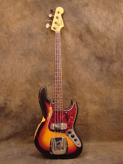
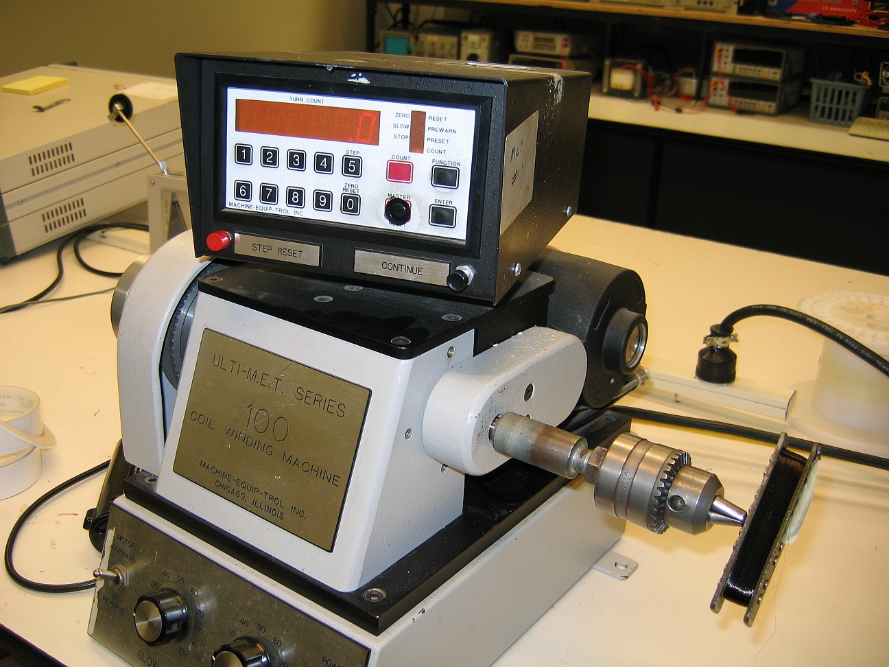
to have an open (disconnected) winding. The rest of this document describes how the pickup was repaired. Click on an image to view a larger version of it. (The bass on the left is a stock photo - not the one with the repaired pickup) |
|
|
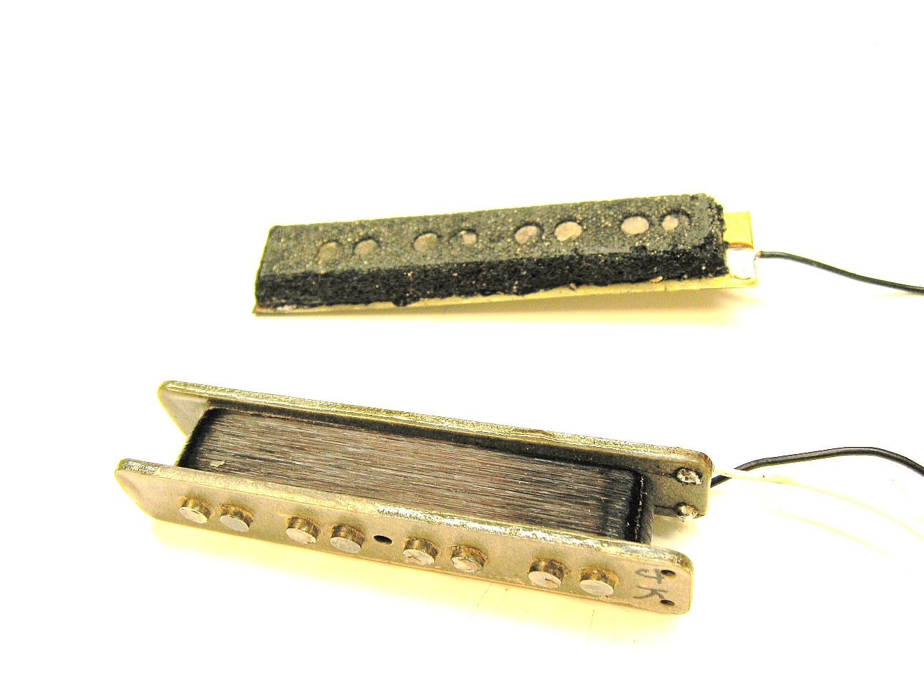
The ground plate and pad were removed in anticipation of rewinding the pickup. |
|
|
|
|
|
|
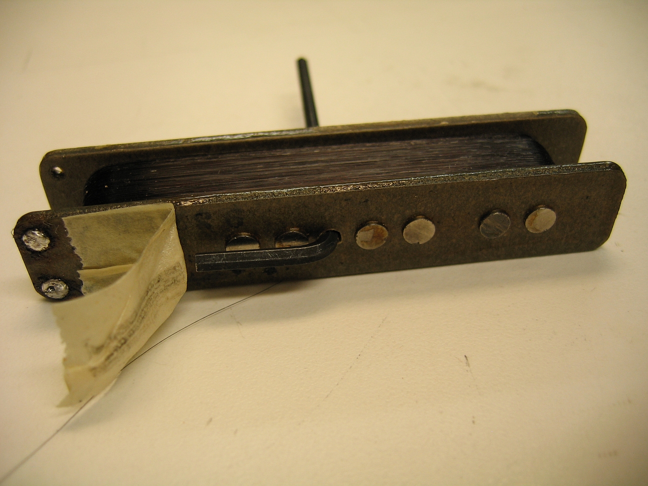
| After unwinding 60 turns the end of the wire came loose, which turned out to be a lucky break (yes, that's a pun). Continuity from the new "Finish" lead was verified using an Exacto knife to cut through the magnetwire insulation and make contact with the copper. The Exacto knife blade was connected to one lead of an ohmmeter with the other lead connected to the Start (White) lead. Since the turns count of the pickup appeared to be 9000 to 10,000 or so* the decision was made to re-terminate the loose end of the Finish with 60 fewer turns on the coil rather than completely unwind and then rewind the coil. This saved quite a bit of time. | |
|
|
My hand-written notes from the repair process at left.
I took 10 feet of the 60 turns that came off and measured the DC
resistance to be 18.281 ohms. AWG 42 can range between
1.504 and 1.801 ohms per foot. Elongation during winding can
increase the number of ohms per foot so 1.8281 ohms per foot is not
unreasonable for a post-wound coil's measurement of AWG 42 magnetwire. See
the
NEMA wire standard for more details.
Based on the actual measurement of ohms per foot and the DCR of the
remaining turns the number of feet of wire would be |
|
|
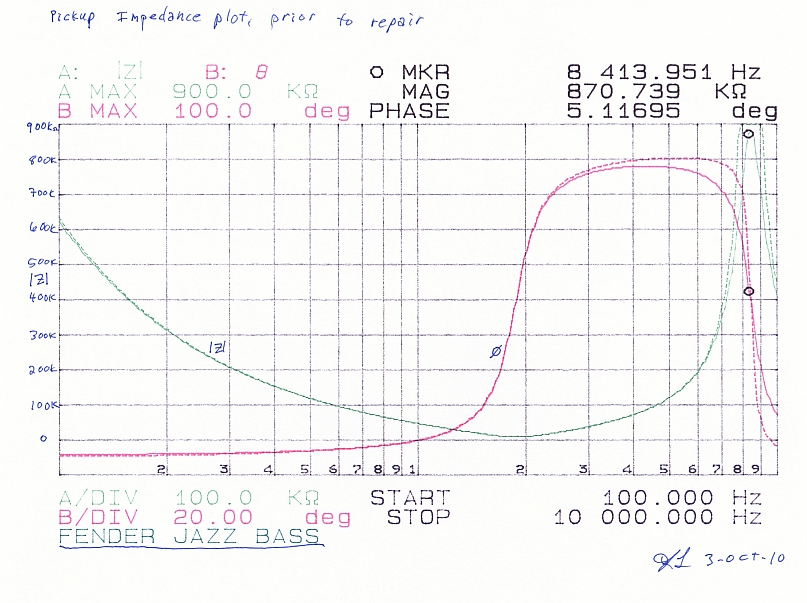
 The impedance plot after making the repair shows the layer-to-layer capacitance is gone now that the coil is no longer open. The prediction of the model and the measured results are again very close except above 7kHz. The pre-repair and post-repair estimates of inductance and series resistance were remarkably similar leading me to think that it would be reasonably easy to rewind a broken pickup to have nearly identical characteristics to the original by measuring its impedance over frequency. The distributed capacitance would be the main characteristic that might be variable due to winding and the pre- and post-repair values are very close (122pF versus 119pF). I didn't try making a turns ratio test by winding a known number of turns around the pickup and closing the magnetic path by shunting the magnet poles but it seems this would be a valid way of making an accurate turns-count measurement. |
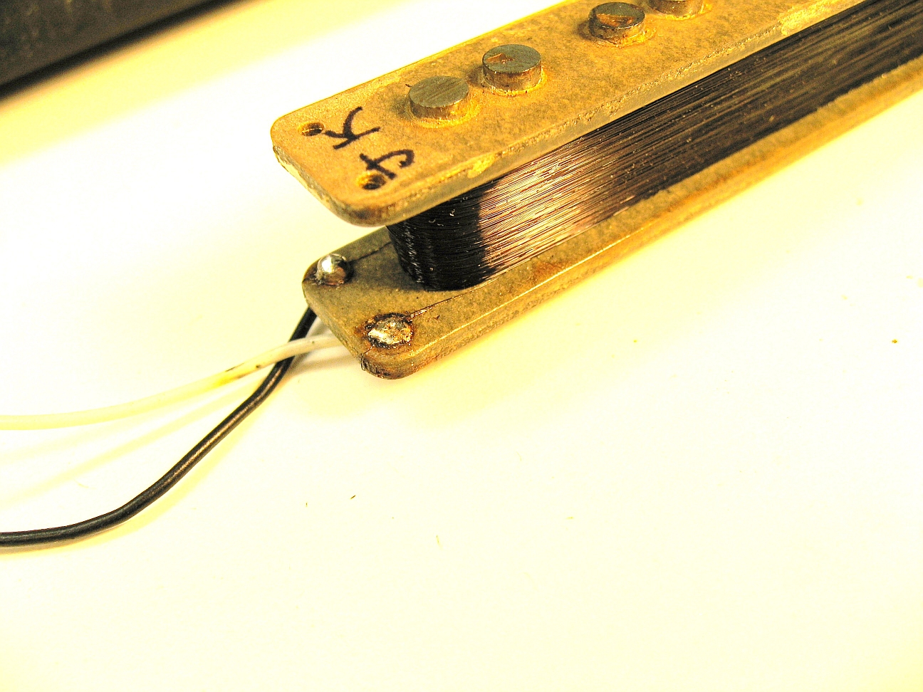
| This particular pickup appears to have been built after 1965 when Fender began using winding machines with controlled pitch versus those wound before that time that may have been hand-guided (see the link below regarding the statistics of Fender pickups). Clicking on the close-up of the pickup above shows the layering to be very even. If this pickup winding should open again I may ask the owner if I can rewind it using a low value for the number of turns per layer which would result in less distributed capacitance than the 119pF measured. As a guess, it might drop that value to perhaps 50pF and move the resonant frequency to something well beyond 10kHz. This would likely cause the tone to become brighter. If that turned out to be undesirable the tone control could be used to add capacitance back across the pickup. Another option would be to add a 68pF capacitor across the winding, restoring it to its post-1965 sound. | |
|
*Here's some good background information on the
statistics of Fender
pickups.
Local Copy (in case this disappears. Again) |
|